Psychrometric chart & calculator
See how temperature, moisture and energy change together. Edit two air states, connect them on the chart, and calculate the air-side duty.
Design conditions
State A · entering
State B · leaving
SI units · dry bulb -1-10–50 °C · ideal moist-air model · known pressure plus two independent properties. The chart and calculator run locally in your browser, including offline.
Clears calculated results and saved marked points. Pressure returns to 101.325 kPa; chart reference lines and the comparison log remain.
Air-state plot
Mark points, drag the bold dots, then connect any two points. Saved points stay in this browser.
Marked points & process lines
Blue curves: RH · Gray diagonals: enthalpy · Purple: wet bulb · Green: specific volume · Orange A → blue B: selected process. Line labels include units; each point has a hover tooltip.
On a narrow screen, scroll the chart horizontally. The connecting line shows the endpoint change, not a validated coil path. Chart-click mode selects dry bulb and humidity ratio; points above saturation are rejected.
Named points & comparison log
Add up to 30 points: outdoor air, return air, mixed air, coil leaving air or supply air. A and B remain the inputs for process load calculations.
Use the From / To selectors above to connect your points. Each saved log entry keeps its original pressure and calculated properties, even after you edit the chart.
Saved in this browser only (maximum 500 readings). Export CSV for a permanent record. Clear all inputs keeps this log; use Remove beside a reading to delete it.
Saved readings
Psychrometric chart guide — September 2026
Open the full illustrated guide (PDF) · Download guide
Use these instructional diagrams to understand the live chart above. The live calculator uses SI units, 0–50°C dry bulb and 60–110 kPa absolute. The guide's I-P examples and recommended future features do not change those supported limits.
Process directions and worked cooling example
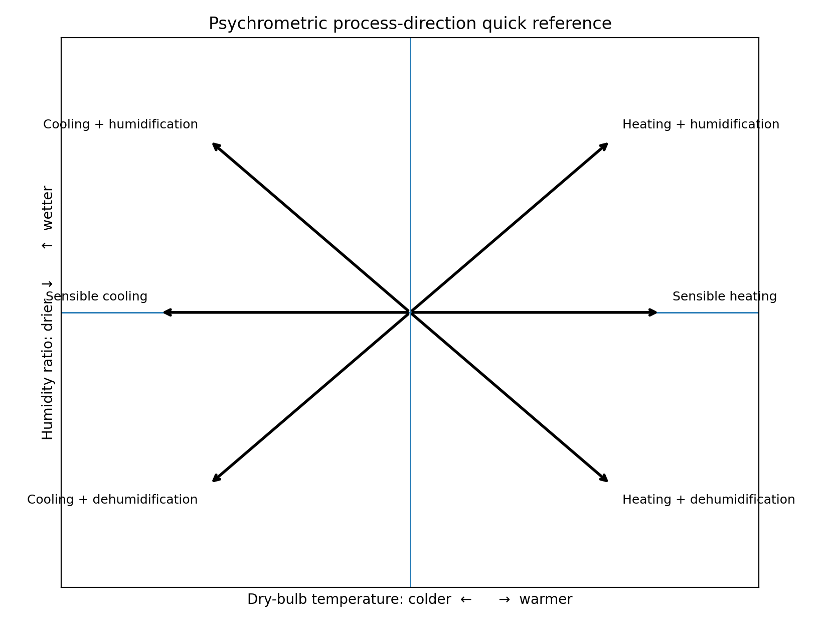
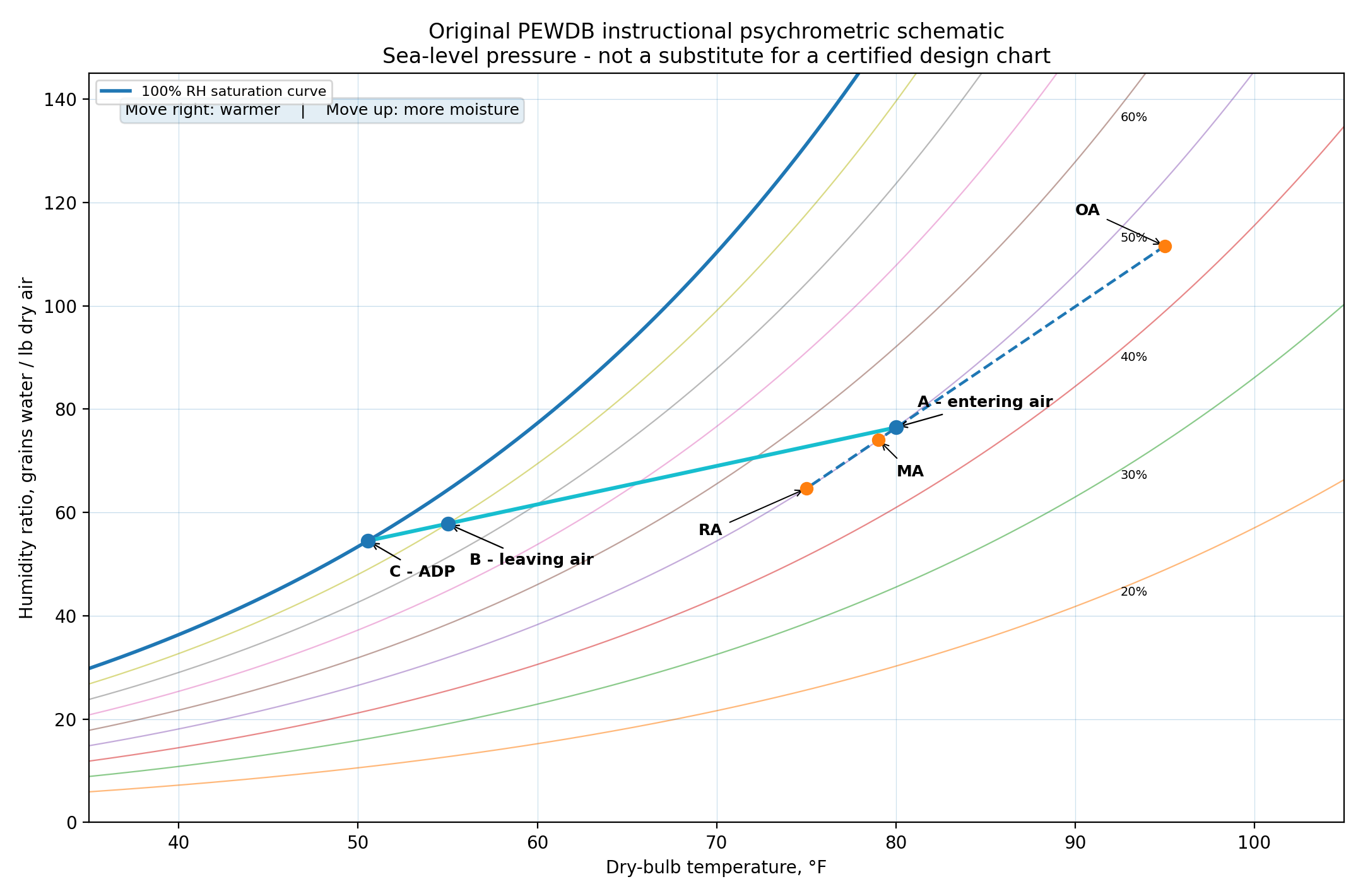
At 101.325 kPa: enter A = 26.6667°C, 50% RH; B = 12.7778°C, 90% RH; 1,000 actual cfm = 0.471947 m³/s. Use ADP about 10.3°C as an illustrative estimate, not a measured coil surface temperature. The source guide's absolute I-P enthalpy values use a different datum from this SI calculator; compare enthalpy differences for loads, not a simple unit conversion of absolute enthalpy.
Mixing fractions must use dry-air mass. The straight line in a temperature–humidity chart is an approximation; exact adiabatic mixing conserves humidity ratio and enthalpy, then solves temperature. Final equipment selection requires actual operating conditions and manufacturer data.
Calculated properties
Process A → B
Positive heat = removal from air. Negative heat = addition to air. Loads use the actual inlet airflow and conserved dry-air mass flow.
Coil air bypass factor
Assess states A and B against a specified saturated apparatus dew point (ADP), or predict B from A, ADP and bypass factor.
BFh = (hB − hADP)/(hA − hADP); BFw = (WB − WADP)/(WA − WADP); BFt ≈ (TB − TADP)/(TA − TADP). Contact factor = 1 − BFh. ADP is an effective saturated surface condition, not automatically refrigerant or water temperature. This is not a measured air-leakage fraction.
Heating equipment: moisture & RH comparison
| Heater / process | Moisture and RH effect | Chart direction | Application and comparison |
|---|---|---|---|
| Electric resistance heater | No moisture added; W and dew point unchanged. RH decreases as dry bulb rises. | Horizontal right: sensible heat only. | Simple modulation; no combustion products. Electricity demand can be high; not a humidifier. |
| Hot water heating coil | No moisture added through an intact coil. W unchanged; RH decreases. | Horizontal right: sensible heat only. | Uses boiler/heat-pump hot water; needs pump, valve and freeze protection. A cold coil can dehumidify, but that is cooling operation. |
| Steam heating coil (indirect) | Steam condenses INSIDE tubes. No moisture added to air; W unchanged, RH decreases. | Horizontal right: sensible heat only. | High heat-transfer capacity; steam trap and condensate drainage required. A leak is a fault, not normal humidification. |
| Gas furnace (indirect, vented) | Combustion gas is separated from supply air. W unchanged; RH decreases. | Horizontal right: sensible heat only. | Fuel heating; heat exchanger and venting required. Condensing-furnace water is on the flue side, not moisture removed from supply air. |
| Direct steam injection humidifier | Adds vapor: W increases. RH normally increases with modest dry-bulb rise; final RH must be calculated. | Upward and slightly right; h increases. | Humidity control; requires absorption distance, suitable steam quality and controls. Different device from a steam coil. |
| Direct-fired / unvented gas heat | Combustion water enters air: W increases. RH may rise OR fall because dry bulb also increases. | Up and right; slope depends on fuel and dilution. | Not equivalent to an indirect furnace. Combustion products, ventilation and permitted application require assessment. |
How to read the chart, all formulas and worked examples
Reading a psychrometric chart
Select the chart pressure first: 101.325 kPa is the example, not a universal site pressure. Use two independent properties to locate a state. On this rectangular T–W chart, dry bulb is the horizontal axis and humidity ratio W is the vertical axis. RH curves bend upward; the 100% curve bounds the unsaturated region. Read W horizontally to the vertical scale. Move left at constant W to the saturation boundary to find dew point. Below freezing this implementation uses saturation over ice and labels the result dew/frost point. Follow a wet-bulb line to saturation to read thermodynamic wet bulb. Diagonal enthalpy and specific-volume lines are separately selectable; wet bulb and enthalpy lines are close but not identical. ASHRAE Fundamentals — Psychrometrics (SI, 2017)
The chart is generated from equations, not traced from a copyrighted chart. It supports -1-10–50 °C dry bulb and 60–110 kPa absolute pressure. Humidity ratio uses g/kg dry air on the chart and kg/kg dry air in equations. At saturation RH = 100% and, above freezing, dry bulb = wet bulb = dew point. At zero moisture dew point has no finite value. A null wet bulb near freezing marks the small ice/liquid convention gap; do not silently substitute zero.
Choose dry bulb with RH, wet bulb, dew/frost point or humidity ratio; alternatively choose enthalpy with humidity ratio to solve dry bulb. Edit A and B, or use a preset. The arrow is the endpoint change A→B; it does not assert that every real coil follows a straight line. The chart redraws at the selected pressure. Off-scale humidity expands the vertical scale automatically. Export SVG to retain the chart and CSV to retain states and loads.
Property relationships and formulas
Use T in °C, K = T + 273.15, P and vapor partial pressure pv in kPa absolute, W in kg water/kg dry air, h in kJ/kg dry air, and v in m³/kg dry air. RH percentage = 100φ. Atmospheric pressure is required; neither temperature alone nor RH alone defines the state.
Saturation vapor pressure: ps(T) = exp(F(K))/1000 kPa. For T > 0.01 °C, F(K) = −5800.2206/K + 1.3914993 − 0.048640239K + 0.000041764768K² − 0.000000014452093K³ + 6.5459673 ln(K). For T ≤ 0.01 °C (ice), F(K) = −5674.5359/K + 6.3925247 − 0.009677843K + 0.00000062215701K² + 0.0000000020747825K³ − 0.0000000000009484024K⁴ + 4.1635019 ln(K). These are ASHRAE perfect-gas psychrometric saturation relations; the chart is not a real-gas fog model. PsychroLib: documented ASHRAE equations and implementation
Relative humidity: φ = pv/ps(T); pv = φ ps(T). Humidity ratio: W = 0.621945 pv/(P − pv). Inverse: pv = P W/(0.621945 + W). Saturated humidity ratio Ws(T,P) uses pv = ps(T). RH is a saturation-pressure ratio, not W/Ws (that is degree of saturation). Specific humidity on a moist-air mass basis is W/(1 + W), which differs from humidity ratio.
Enthalpy: h = 1.006T + W(2501 + 1.86T). The zero reference is dry air and liquid water at 0 °C. Dry bulb from h and W: T = (h − 2501W)/(1.006 + 1.86W). Humidity ratio from h and T: W = (h − 1.006T)/(2501 + 1.86T). Dry bulb from W and RH can also be obtained by solving ps(T) = P W/[(0.621945 + W)φ], provided φ > 0 and the solution is physical.
Dew/frost point: solve ps(Tdp) = pv. The plotter brackets −100 °C to dry bulb and uses 60 bisection iterations. If pv < ps(−100 °C), it reports outside range / undefined rather than an invented finite value. Below 0.01 °C the ice saturation convention returns frost point. A liquid-water dew point below freezing would require a different convention.
Thermodynamic wet bulb Tw: solve W = [(2501 − 2.326Tw)Ws(Tw,P) − 1.006(T − Tw)]/[2501 + 1.86T − 4.186Tw] for Tw ≥ 0 °C. For Tw < 0 °C, use W = [(2830 − 0.24Tw)Ws(Tw,P) − 1.006(T − Tw)]/[2830 + 1.86T − 2.1Tw]. The calculator uses bisection in the applicable branch. These equations account for water/ice enthalpy; constant enthalpy is only an approximation to constant wet bulb. A real wetted thermometer also depends on radiation, air speed, wick condition and pressure. PsychroLib: documented ASHRAE equations and implementation
Specific volume v = 0.287042(T + 273.15)(1 + 1.607858W)/P. Moist-air density ρ = (1 + W)/v, in kg moist air/m³. Dry-air mass per volume ρda = 1/v, in kg dry air/m³. Do not use 1/v as total moist-air density. Warmer air at fixed P and W has higher v and lower density. More vapor at fixed P and T lowers moist-air density. W, h and v here are all based on one kilogram of DRY air.
Heat loads SHR and condensate formulas
The two-state tool uses ACTUAL inlet airflow Qv in m³/s, not standard airflow. Dry-air mass flow mda = Qv/vA; inlet moist-air mass flow = mda(1 + WA). At steady state without leakage, dry-air mass flow is conserved even when moisture condenses. State A is entering and B is leaving. Positive heat means heat REMOVED from air; heating produces negative heat values.
Total air-side enthalpy removal Qt = mda(hA − hB), kW. For a consistent algebraic split with the stated linear enthalpy model, Wavg = (WA + WB)/2 and Tavg = (TA + TB)/2. Sensible Qs = mda(1.006 + 1.86Wavg)(TA − TB). Latent component Ql = mda(2501 + 1.86Tavg)(WA − WB) = Qt − Qs. This is an exact split of the approximate enthalpy equation; alternative engineering conventions allocate the small cross-term differently. The common shortcut Qs ≈ 1.006mdaΔT omits vapor heat capacity. Ql ≈ mwater hfg is a separate approximation and need not give the identical split.
SHR = Qs/Qt. If Qt ≈ 0, SHR is undefined. It normally lies between 0 and 1 for simultaneous sensible cooling and dehumidification; other processes can yield values outside that interval. Do not force all processes into 0–1. Heating at constant W gives SHR = 1 under this signed convention. Adiabatic evaporative cooling has nearly zero total enthalpy change and is not usefully characterized by that SHR.
Net water removal mwater = mda(WA − WB), kg/s. Condensate rate = 3600 max(0,mwater), kg/h, numerically close to L/h for liquid water near room temperature. If W increases, display moisture added = 3600 max(0,−mwater). Actual drain delivery can differ because of retention, re-evaporation and carryover. Air must contact a surface below its dew point to condense; merely decreasing RH is not dehumidification.
For cooling with liquid condensate drained at Tc, coil heat removal ≈ mda(hA − hB) − mcond·4.186Tc, kW, with mcond in kg/s and liquid enthalpy referenced to 0 °C. This corrected value is distinct from the common air-side load Qt. It excludes fan heat, casing heat gain and storage. For moisture-adding processes, the displayed air enthalpy change is not equipment electrical input; injected water/steam brings its own enthalpy.
Worked psychrometric chart examples
Example 1 — sensible heating: P = 101.325 kPa, A = 20 °C and 50% RH, B = 35 °C at the SAME humidity ratio. The path moves right horizontally. W and dew point stay constant, h and v increase, density decreases and RH drops to about 20.8%. At 0.50 m³/s inlet actual airflow, condensate is zero. Use the Heating preset to see all calculated values.
Example 2 — cooling and dehumidification: A = 30 °C, 60% RH; B = 12 °C, 95% RH; P = 101.325 kPa and inlet flow = 0.50 m³/s. Although RH rises, W decreases and water condenses. The path moves down and left. The tool calculates sensible/latent/total removal, SHR and condensate. This pair is an assumed coil duty, not a manufacturer coil selection. The actual path and bypass factor depend on surface conditions.
Example 3 — reheat: A = 12 °C and 95% RH, B = 22 °C at constant W. The line moves right without further moisture removal. RH falls, but W stays at the coil-leaving value. This distinguishes dehumidification at the cold coil from RH reduction during reheat.
Example 4 — idealized adiabatic evaporative cooling: A = 35 °C and 25% RH, B = 24 °C at the same h. W increases while dry bulb decreases. Constant h approximates adiabatic evaporation when water enthalpy and losses are neglected; exact constant wet bulb differs slightly. ASHRAE — Evaporative cooling
Example 5 — steam addition: A = 20 °C and 30% RH; add ΔW = 0.004 kg/kg dry air with assumed steam enthalpy 2676 kJ/kg. Set WB = WA + ΔW and hB = hA + ΔW·2676, then solve TB. The preset is an ideal mass/energy balance with complete vapor absorption. Steam pressure, quality, losses and absorption distance require actual equipment data. Spirax Sarco — Direct steam injection humidifiers
Heating equipment moisture and relative humidity
For electric resistance, hot-water and intact indirect steam coils, the heating medium does not mix with air: moisture content stays constant and RH falls as dry bulb increases. An indirect gas furnace separates flue gas from supply air and behaves similarly. Steam condensing in a heating coil does not mean it humidifies the air. Heating does not destroy water vapor.
Direct steam injection is different: it increases W and h. Under ordinary humidification control RH increases, but calculate final T and RH from the energy and moisture balance. Unvented/direct-fired combustion introduces water vapor and combustion products to air. Because both temperature and moisture rise, its RH direction cannot be prescribed universally. DOE identifies moisture release to conditioned space from unvented heaters. US DOE — Combustion appliance safety and efficiency
Compare like-for-like air-side states rather than claiming fixed efficiency rankings from psychrometrics. Electrical demand, boiler efficiency, fuel efficiency, pump/fan power and part-load performance are separate energy-system calculations. The comparison table describes normal moisture effects, applications and practical differences, not universal product efficiency.
Coil air bypass factor and contact factor
Apparatus dew point (ADP) is the effective saturated condition used in a simplified wet-coil model. It is not necessarily the refrigerant or entering-water temperature. A thermal bypass factor describes incomplete air-to-coil approach; it is not proof that this percentage of air physically leaks around the coil. EnergyPlus engineering reference — coil bypass factor
Use BFh = (hB − hADP)/(hA − hADP) and BFw = (WB − WADP)/(WA − WADP). The familiar temperature approximation is BFt = (TB − TADP)/(TA − TADP). Contact factor = 1 − BF. The plotter reports all three ratios without silently clamping inconsistent results. Ratios should be 0–1 for this wet-coil model. The 0.02 spread warning is an illustrative consistency screen, not a manufacturer acceptance tolerance.
To predict leaving air, set WB = WADP + BF(WA − WADP) and hB = hADP + BF(hA − hADP), then TB = (hB − 2501WB)/(1.006 + 1.86WB). This preserves dry-air-basis moisture and enthalpy mixing. BFt can differ slightly from BFh and BFw. For the temperature approximation, TADP = (TB − BFt TA)/(1 − BFt), undefined at BFt = 1; verify the resulting saturated state against moisture data.
Example: choose A = 30 °C, 60% RH at 101.325 kPa; specify ADP = 10 °C and BF = 0.10. Click Predict State B from ADP + BF. Contact factor is 0.90, and the leaving state is calculated from both moisture and energy balances. BF = 0 reaches saturated ADP; BF = 1 leaves entering air unchanged. Dry coils, freezing coils, reheat, fan heat and partly wet surfaces need a different or expanded model.